What Is a 480V to 13.8kV Step Up Power Transformer?
A 480V to 13.8kV step-up power transformer raises low-voltage industrial power to medium voltage for utility interconnection, campus distribution, or long-distance transfer. It is not simply a larger voltage converter. Its design must control insulation stress, inrush current, heat, sound, and fault energy. The 13.8kV side commonly serves medium-voltage switchgear, feeders, and generators.
Global demand makes this equipment increasingly important. The International Energy Agency’s Electricity 2024 report projects worldwide electricity demand growth of about 3.4% annually from 2024 through 2026. More generation and electrification require reliable voltage transformation. However, rising demand does not justify selecting the largest transformer available. Oversizing can increase losses, cost, and installation complexity.
This article examines 480v To 13.8kv Step-Up Power Transformer Specs, including rated capacity, frequency, impedance, cooling method, insulation level, tap range, vector group, and short-circuit withstand. IEEE C57.12.00 and IEC 60076 provide widely recognized technical frameworks for transformer ratings, testing, and performance. The U.S. Department of Energy also treats transformer efficiency as a major equipment consideration because losses continue throughout energized service.
Real projects are messier. A nameplate voltage alone cannot confirm compatibility. Engineers must review generator output, load diversity, grounding, cable length, ambient temperature, and available fault current. A 2,000 kVA oil-immersed unit may look suitable on paper, yet its 7.5% impedance could alter protection coordination. That detail matters. Careful field measurements and verified manufacturer data remain more reliable than a generic catalog table.
Definition and Purpose of a 480V to 13.8kV Step-Up Transformer
What Is a 480V to 13.8kV Step Up Power Transformer?
A 480V to 13.8kV step-up transformer raises low-voltage power to medium voltage. Its voltage ratio is approximately 28.75:1. This equipment commonly connects a 480V generator, industrial bus, or facility power system to a 13.8kV distribution network. Higher voltage allows the same power to travel with lower current. That reduces conductor losses and supports longer feeder distances.
Consider a 1 MVA, three-phase system. At 480V, the line current is roughly 1,203 amperes. At 13.8kV, it falls to about 42 amperes, excluding losses and operating differences. The transformer must manage insulation strength, grounding, short-circuit forces, temperature rise, and switching inrush. A poor grounding design can undermine an otherwise sound installation.
The purpose is practical, not merely mathematical. The IEA’s Electricity 2024 report projects data-centre electricity use could exceed 1,000 TWh globally by 2026. Expanding industrial and digital loads increase pressure on medium-voltage infrastructure. A 13.8kV connection can make those loads easier to distribute across a site. However, the ratio alone does not define suitability. Engineers must verify power factor, impedance, harmonics, protection coordination, and available fault current. Field measurements matter. The paper design can still fail. Transformer efficiency, loading patterns, ventilation, and local utility requirements should be checked against applicable IEEE and IEC guidance before energization.
How Voltage Is Increased from 480V to 13.8kV
A 480V to 13.8kV step-up power transformer raises electrical voltage for medium-voltage distribution. It normally receives 480V AC on its low-voltage winding and delivers 13,800V AC on its high-voltage winding. The change depends on the turns ratio between the two windings.
The ideal ratio is 13,800 divided by 480, or about 28.75 to 1. The high-voltage winding therefore has many more turns. As voltage rises, current falls by a similar proportion when power remains nearly constant. Real transformers lose some energy through winding resistance, core heating, and magnetic effects. The simplified ratio helps, but it is not the whole design.
During operation, the iron core carries alternating magnetic flux between the windings. It transfers energy without a direct electrical connection. Insulation, clearances, bushings, grounding, and protective relays must withstand the 13.8kV side. Tap settings may adjust the output when the incoming 480V supply changes. Testing usually includes winding resistance, insulation condition, turns ratio, and protective-device checks.
A common mistake is treating 13.8kV as merely “480V multiplied.” Phase configuration matters. In a three-phase system, engineers must confirm whether the stated voltages are line-to-line or line-to-neutral. That detail can change the calculated ratio and connection method. Field measurements should never replace approved drawings and qualified testing procedures.
Main Components and Internal Construction
What Is a 480V to 13.8kV Step Up Power Transformer?
A 480V to 13.8kV step-up power transformer raises low-voltage electricity for medium-voltage distribution. Its approximate turns ratio is 28.75:1. Inside the tank, a laminated steel core guides magnetic flux with controlled losses. Copper or aluminum windings surround the core legs. The 480V winding uses thicker conductors because it carries higher current. The 13.8kV winding uses more turns and stronger insulation between layers.
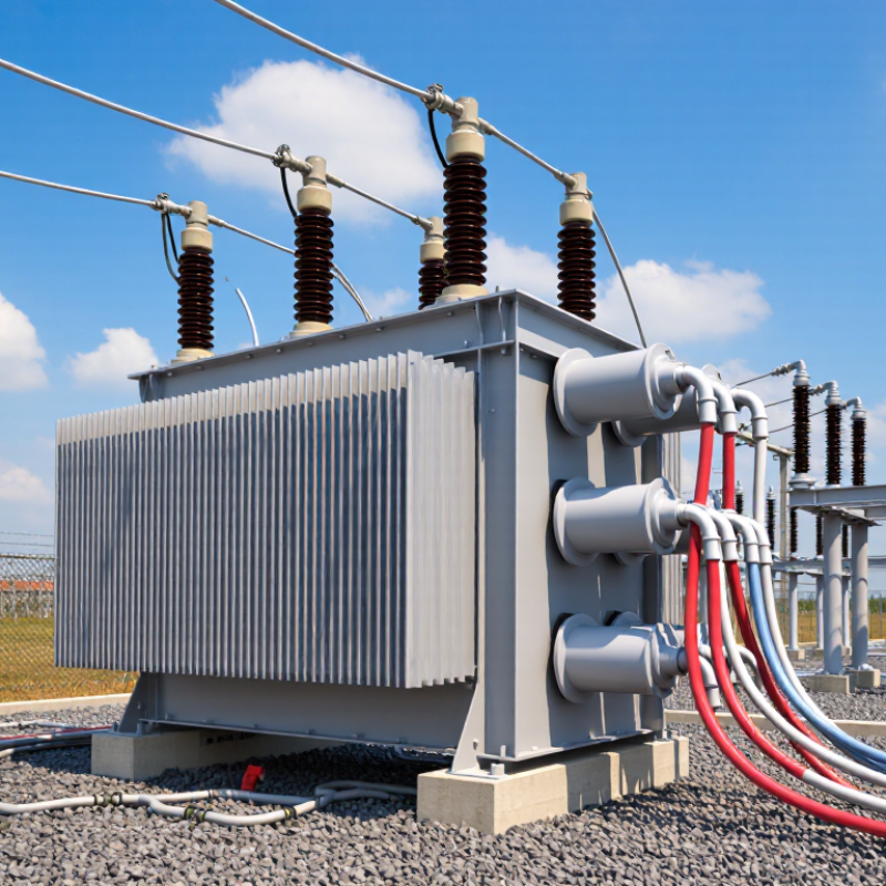
The core and coils are secured inside a sealed tank filled with insulating oil, or installed in a dry-type enclosure. Pressboard barriers, enamel coatings, and spacers help prevent internal flashover. Bushings carry each conductor safely through the tank wall. A tap changer can adjust the output voltage when system conditions change, although its operating range must be verified carefully. Radiators release heat from the oil. Temperature indicators, pressure relief devices, and liquid-level gauges support safer operation. One detail is often underestimated: loose clamping parts can create vibration, noise, and future insulation damage. Field assumptions should be checked against test records.
Tips: Confirm the nameplate voltage, frequency, impedance, and connection group before installation. Inspect winding resistance, insulation resistance, and transformer oil condition using qualified procedures. Keep cable clearances practical, not merely compliant. A small spacing mistake can become a serious failure. I would also review grounding connections twice, because a neat installation can still hide a weak return path.
Electrical Ratings, Insulation, and Safety Requirements
What Is a 480V to 13.8kV Step Up Power Transformer?
A 480V to 13.8kV transformer raises industrial voltage for medium-voltage distribution. Its nominal turns ratio is approximately 1:28.75. The transformer’s kVA rating must match the connected load, starting current, and future expansion. A 1,000 kVA unit, for example, supplies about 41.7 amperes at 13.8kV under balanced conditions. Actual current depends on efficiency, power factor, and operating voltage.
The insulation system needs careful attention. Engineers evaluate winding insulation, phase-to-ground clearances, dielectric strength, and basic impulse insulation level. A 13.8kV winding commonly requires a much higher insulation level than its operating voltage suggests. That margin handles lightning impulses and switching surges. Oil-filled and dry-type designs behave differently during heat removal and fault conditions. The ratio is not the whole design. Tap settings also affect output voltage, especially when the 480V source fluctuates.
Safety begins with a properly grounded enclosure and an engineered grounding electrode system. Medium-voltage equipment requires suitable fuses or circuit breakers, surge protection, visible isolation, and mechanical interlocks. Arc-flash labels should reflect verified fault-current calculations, not guesswork. During commissioning, technicians should inspect bushings, torque connections, test insulation resistance, and confirm phase relationships before energizing. A missed neutral connection can create confusing measurements. It is an easy mistake, but potentially serious. Installation details must follow the applicable electrical code, utility requirements, and the transformer manufacturer’s tested limits.
480V to 13.8kV Step-Up Transformer: Electrical Ratings, Insulation, and Safety
This representative comparison shows the rated winding voltages and commonly referenced ANSI insulation levels for a transformer stepping up 480V to a 13.8kV distribution voltage. A 13.8kV winding is generally designed in the 15kV voltage class, while the 480V winding falls within the 1.2kV class.